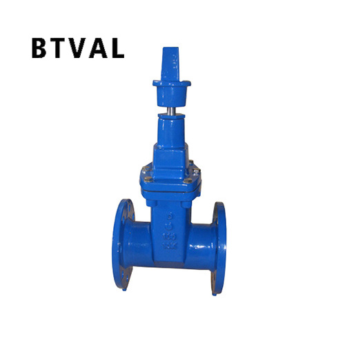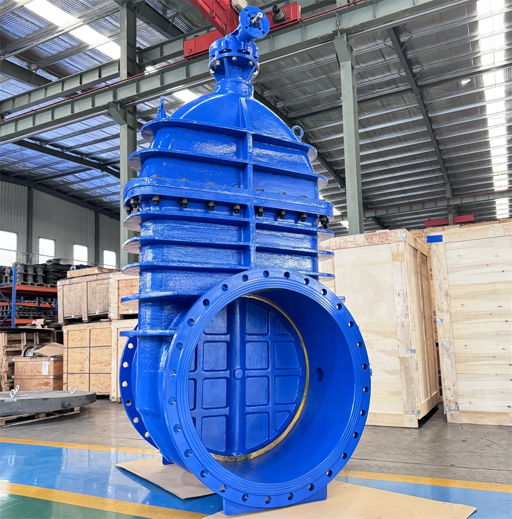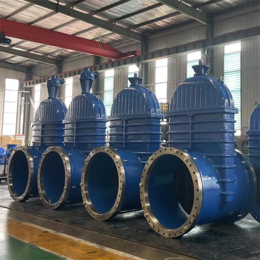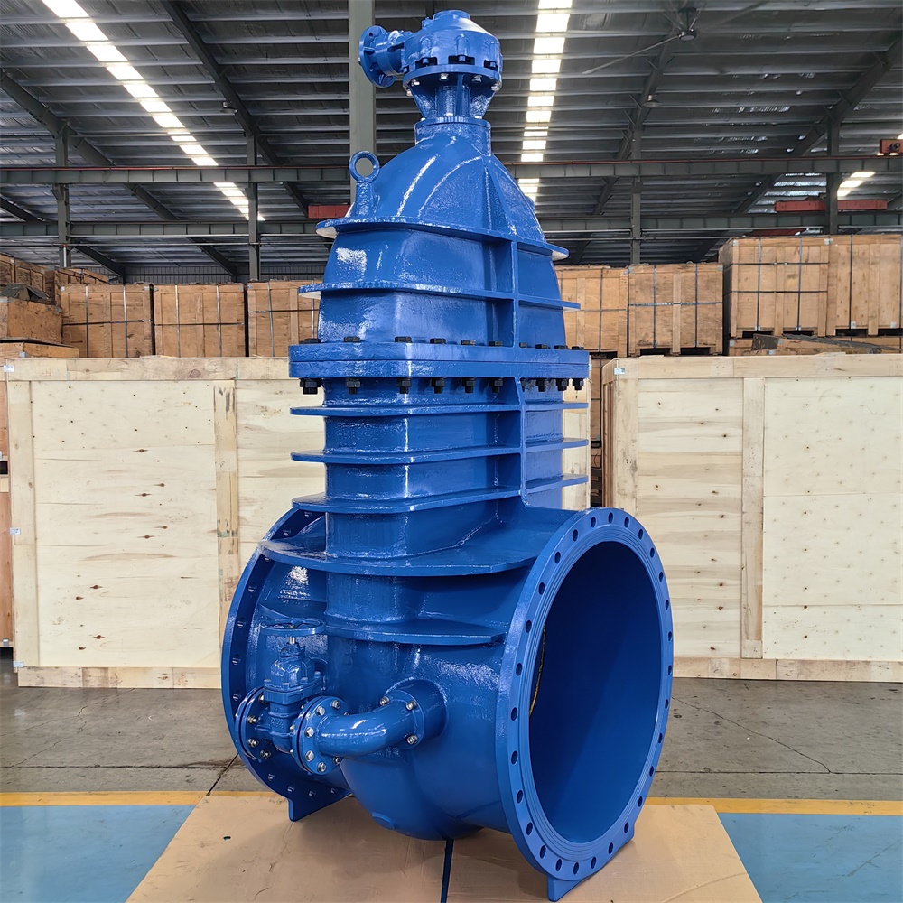

The opening and closing parts of the soft-sealed gate valve are gates. The moving direction of the gate is perpendicular to the fluid direction. The gate valve can only be fully opened and closed, and can not be adjusted and throttled. The gate has two sealing surfaces. The two sealing surfaces of the common mode gate valves form wedges. The wedge angle varies with the valve parameters, usually 50. When the medium temperature is not high, it is 2 52'.
Soft-sealed gate valves are divided into open-rod soft-sealed gate valves and dark-rod soft-sealed gate valves. Usually there are trapezoidal threads on the lifting rod. Through the nut in the middle of the gate and the guide groove on the valve body, the rotational motion is changed into linear motion, that is to say, the operating torque is changed into the operating thrust. When opening the valve, when the gate lifting height is equal to 1:1 times the valve diameter, the flow passage is smooth, but when running, this position can not be monitored. In practical use, the vertex of the valve stem is used as the sign, that is, the position of the valve stem that is not moving is used as its full open position. In order to consider the lock phenomenon of temperature change, usually open to the vertex position, and then back to 1/2-1 circle, as the position of the full open valve. Therefore, the full open position of the valve is determined by the position of the gate (i.e. stroke). Valves of this type shall generally be installed horizontally in pipes.
Main dimensions of Korean Standard:
| Specifications | Diameter D | Total length L | Connection dimensions | |||||
| Flange outer diameter D | Diameter of protruding part of flangeg | Flange size | Specification of bolts | |||||
| Centre distance of flange hole C | Bulge | Flange thickness | ||||||
| 50 | 50 | 180 | 155 | 100 | 120 | 4 | 19 | M16 |
| 80 | 80 | 240 | 200 | 133 | 160 | 4 | 19 | M16 |
| 100 | 100 | 250 | 220 | 153 | 180 | 8 | 19 | M16 |
| 125 | 125 | 260 | 250 | 183 | 210 | 8 | 23 | M20 |
| 150 | 150 | 280 | 285 | 209 | 240 | 8 | 23 | M20 |
| 200 | 200 | 300 | 340 | 264 | 295 | 8 | 23 | M20 |
| 250 | 250 | 380 | 395 | 319 | 350 | 12 | 23 | M20 |
| 300 | 300 | 400 | 445 | 367 | 400 | 12 | 23 | M20 |
| 350 | 350 | 430 | 505 | 427 | 460 | 16 | 23 | M20 |
| 400 | 400 | 470 | 565 | 477 | 515 | 16 | 27 | M24 |
| 450 | 450 | 500 | 615 | 527 | 565 | 20 | 27 | M24 |
| 500 | 500 | 530 | 670 | 582 | 620 | 20 | 27 | M24 |


